Description:
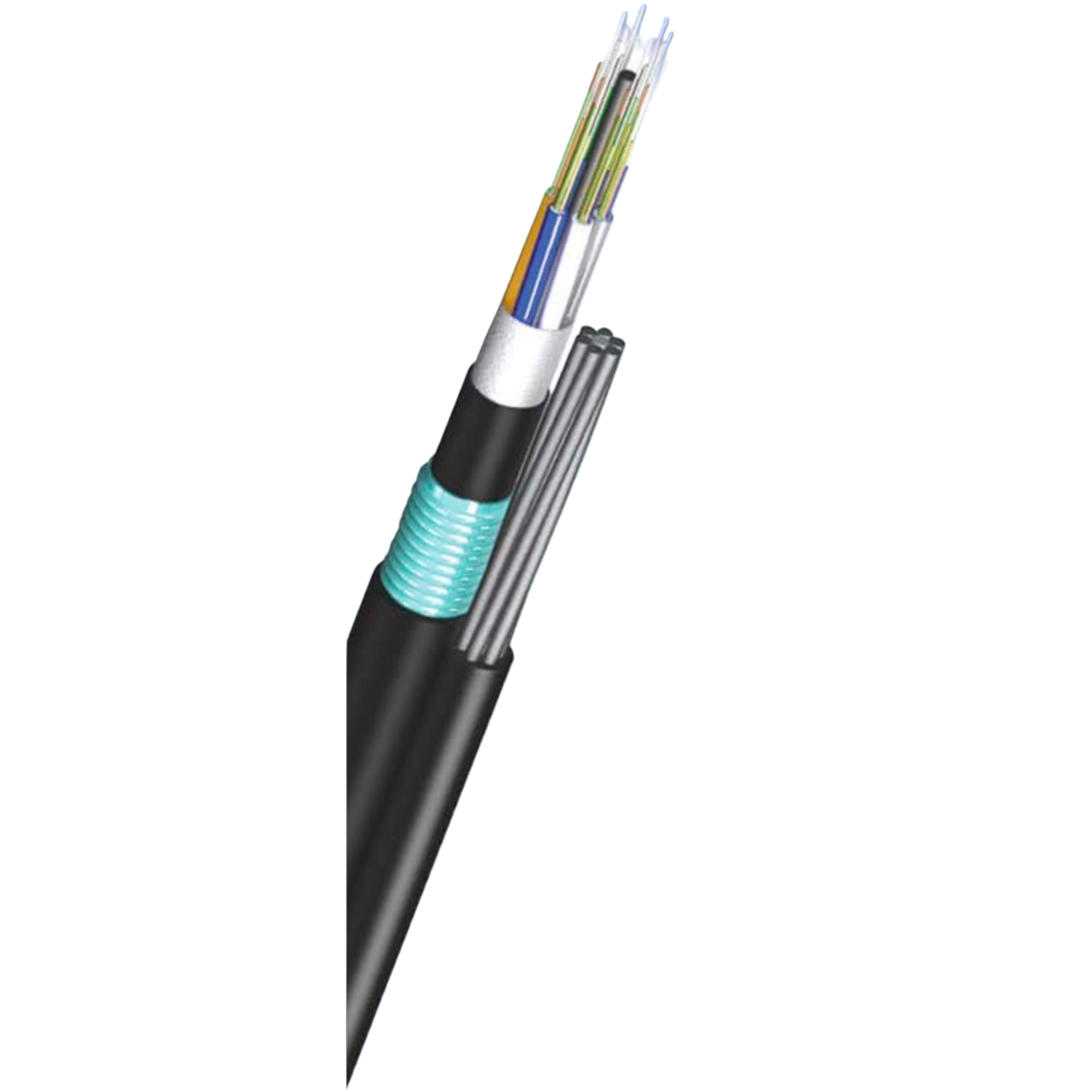
Designed for aerial fiber optic installations, providing self-supporting structural integrity.
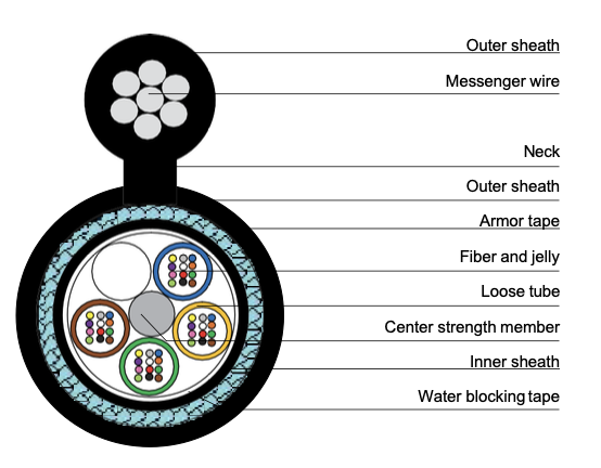
Cross Section Drawing:
Features:
- S-Z stranded (up to 288 fibers) or central tube structure (up to 24 fibers)
- Metallic, all-dielectric armored or unarmored
- Steel wire or FRP for center strength member
- The messenger wire can be steel wire or FRP
- Good water penetration, mechanical and environmental performance
- PE or LSZH sheath materials
- In accordance with IEC, ITU and EIA standards
Specifications:
Unarmored, Loose Tube Stranded
| Cable Type | Fiber Count | Nominal Diameter (W×H mm) | Nominal Weight (kg/km) | Nominal Pulling Force (N) | Nominal Crush Resistance (N/10cm) |
|---|---|---|---|---|---|
| IFC-24-FSF-S1 | 24 | 9.1×16.6 | 135 | 3000 | 1500 |
| IFC-24-SSF-S1 | 24 | 8.1×15.6 | 130 | 3000 | 1500 |
Metallic Armored, Loose Tube Stranded
| Cable Type | Fiber Count | Nominal Diameter (W×H mm) | Nominal Weight (kg/km) | Nominal Pulling Force (N) | Nominal Crush Resistance (N/10cm) |
|---|---|---|---|---|---|
| IFC-24-FStSF-S1 | 24 | 10.3×17.8 | 175 | 3000 | 2000 |
| IFC-24-SStSF-S1 | 24 | 9.3×16.8 | 170 | 3000 | 2000 |
| IFC-24-FAlSF-S1 | 24 | 10.1×17.6 | 155 | 3000 | 2000 |
| IFC-24-SAlSF-S1 | 24 | 9.1×16.6 | 150 | 3000 | 2000 |
Central Tube Structure
| Cable Type | Fiber Count | Nominal Diameter (W×H mm) | Nominal Weight (kg/km) | Nominal Pulling Force (N) | Nominal Crush Resistance (N/10cm) |
|---|---|---|---|---|---|
| IFC-24-CSF-S1 | 24 | 6.5×13.7 | 115 | 3000 | 1500 |
| IFC-24-CStSF-S1 | 24 | 8.0×15.2 | 145 | 3000 | 2000 |
| IFC-24-CAlSF-S1 | 24 | 8.0×15.2 | 130 | 3000 | 1500 |